Hydraulic Steering Installation
As early as 1997, we knew we wanted to install a hydraulic steering system on Highlander, but it was low on our priority list. After breaking the saginaw steering box while being pulled out of a DEEP hole at the last run of '98, we decided that we had to install the hydraulic steering before starting the 1999 mudding season. Here's how our hydraulic steering installation went. |
1. |
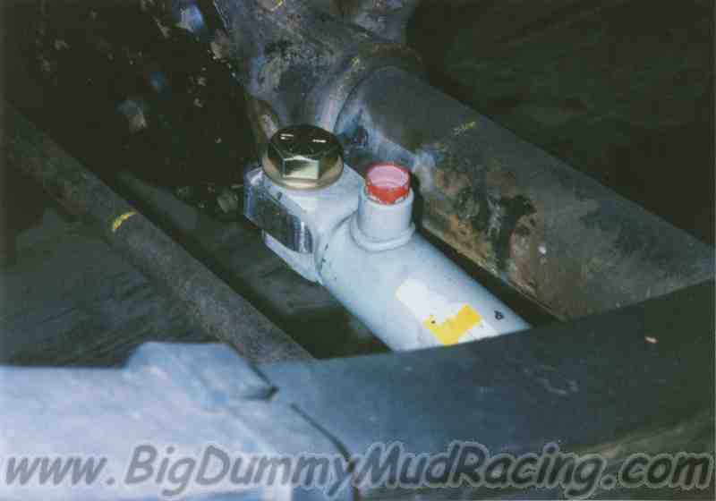
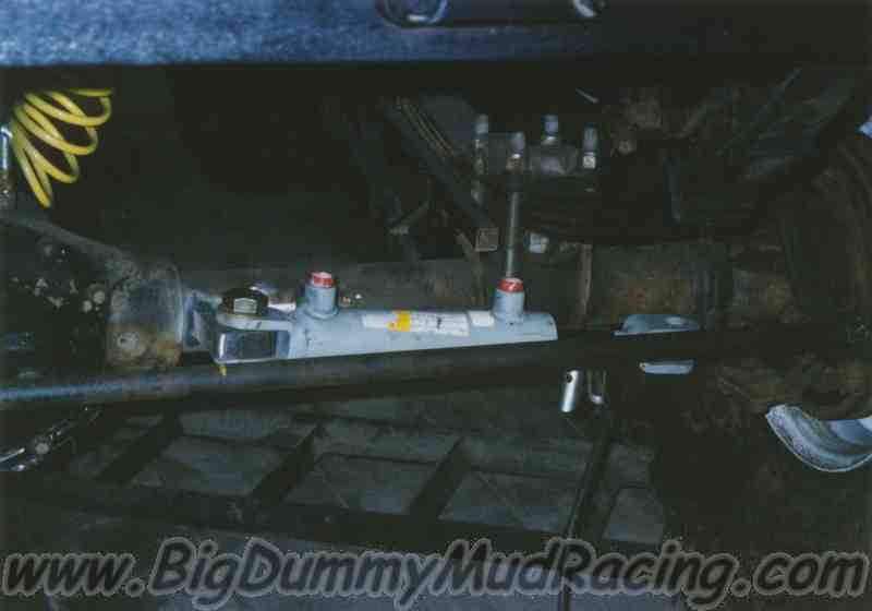
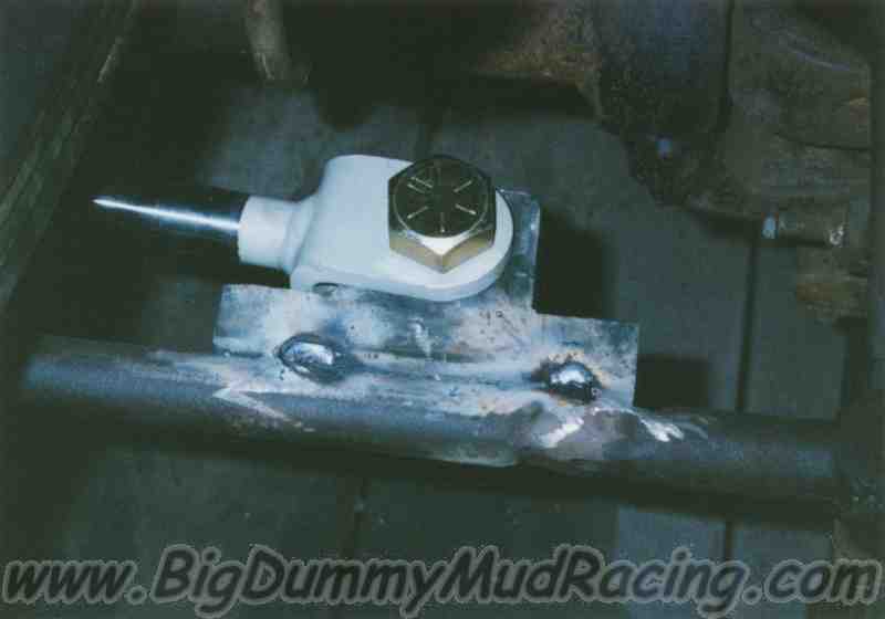
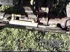
Find the steering valve. We purchased our steering valve from a local used tractor parts company, basically a junkyard for farm equipment. Our particular valve came from the steering on a Massey combine, and cost us about $45.00. Since the valve isn't what caused the tractor to be scrapped in the first place, and don't usually go bad, the junkyards have a ton of them laying around that they are glad to get rid of at a reasonable price. You can also get the valves from Boyce Equipment, but they are considerably more expensive, and basically the same valve. 
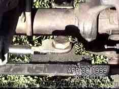
When you pick out a valve, make sure you know how you will run the hydraulic lines to it. A few of the valves that I saw had less or more than 4 ports. While there must be a way to run the hydraulic lines for these valves, they may not work with a stock power steering pump, so be careful. I selected a valve with 4 ports, and couldn't be turned by hand but didn't seem seized. According to the junk yard, this type of valve shouldn't be able to be turned by hand unless connected to hydraulic power. After purchasing the valve, I went to a local hydraulics company to have the valve tested to make sure that it worked. We simply connected their hydraulic power unit to the input and output ports. Then, once power was applied, I was able to turn the valve and verify that hydraulic fluid was sent to the left and right side ports of the valve. |
2. |
Once we knew that the valve worked, I had to modify the input shaft of the valve to accept a standard universal joint yoke with a keyed bore. As the valve came, it had a splined input shaft, and the original u-joint yoke was no longer attached. Since finding the correct yoke was not likely, I decided to pick up a yoke from a farm supply store, and modify the input shaft. It was turned down to .750" diameter, and machined for a keyway to allow it to be connected to our existing steering setup. As it worked out, the yoke that I had purchased used the same u-joint as what was already in our truck (donated from a 1970's Scout). |
3. |
With the valve prepared, we now had to mount the valve. Jason fabricated a bracket that mounted the valve to the body mount framework that we had built.
The steering's intermediate shaft was then lengthened to fit the new steering location. |
4. |
Next we mounted the steering cylinder to the front axle. In order to fit the cylinder, the unused shock absorber mount was cut off of the axle tube. The cylinder that we used was a 2" bore, 6.5" stroke with tie rod yokes at both ends purchased from a discount hydraulics shop. The stroke length was measured by lifting the front of the truck, and measuring how far the tie rod moved from extreme left to extreme right wheel travel. We chose a cylinder stroke that was slightly shorter than the distance we measured. This allows the cylinder to stop itself, and puts less stress on the front axle when in tight left or right turns. |
With the position of the cylinder determined,
we fabricated the blocks that would mount the cylinder to the axle and
the tie rod. These blocks were cut out of 1" thick steel
plate. The fixed mount, which was welded to the axle tube, was a
rectangular block that was relieved to match the radius of the axle tube
on one end. We then drilled a 1" hole through the block to
finish the mount.
We tack welded the mount to the axle tube. We will make the final welds later, after we have made sure everything looks right. |
For modifications such as this, stick welders are the only way to go. Unless you have a really good wire feed, you just don't get the weld penetration that you need. |
5. |
Since the stock power steering pump runs off of the motor, we had concerns that if the truck ever died, we wouldn't be able to steer. To prevent this, we decided to install an auxilliary power unit in the system. The power unit is simply a hydraulic pump powered by a high power electric motor similar to a starter motor, and was purchased from Grainger Industrial Supply. As it happened, since our battery is mounted in the bed of the truck, the existing battery tray made a perfect mount for the aux. power unit. Now that all of our components
were installed, we needed to determine what kind of fittings and hoses
would be required to hook up all of our goodies. We also had to
design the hydraulic circuit to run the system. Here is the
resulting circuit: |
Item | Qty | Description | Item | Qty | Description | |
1. 2. 3. 4. 5. 6. 7. 8. 9. |
4 10 1 3 2 2 2 |
3/8 MJIC X 3/8
MOFS 45° ELL 3/8 MJIC X 3/8 NPTM CHECK VALVE - 3/8 NPTF EA END 3/8 TEE 3/8 NPT COUPLING COMPRESSION FTG. 3/8 TUBE X 3/8 NPTM 3/8 MJIC X 3/8 MOFS X 90° ELL |
10. 11. 12. 13. A. B. C. D. |
2 2 2 1 5 2 1 1 |
3/8 NPT STREET
ELBOW 1/2 MOFS X 3/8 JICM X 90° ELL 3/8 NPT NIPPLE 1/2 MOFS X 3/8 JICM HOSE - 15" 3/8 JICF EA. END HOSE - 36" 3/8 JICF EA. END HOSE - 57" 3/8 JICF EA. END HOSE - 49" 3/8 JICF EA. END |
|
6. |
Installation of the components
was fairly straight forward, though it took more than 4 hours. A
disproportionate amount of time was spent wrestling with the power
steering pump, and trying to get the compression fittings to fit over
the stock steel tubing. Much of the trouble centered around the
distortion caused by the bends put in the tubing at the factory.
Also, there wasn't much room left for the fittings once the stock ones
were cut off. Routing the rest of the system went well, and I was
very cautious to fill the cylinder, and as many of the lines as possible
to make working the air out later easier. |
7. |
With installation complete, I moved on to testing the system. Since I was performing the installation while the truck was still on the trailer, I disconnected the cylinder from the tie rod before starting the truck. This made sure that if something went wrong, and the cylinder extended or retracted completely, there would be no danger of the truck coming off of the trailer. As things worked out, however, the test proved that the system worked flawlessly (except for a little air left in the lines). I reconnected the cylinder to the tie rod, and made sure that it could turn the tires with the full weight of the truck on them. There were no problems, and haven't been any yet! |