2001 Improvements - Frame

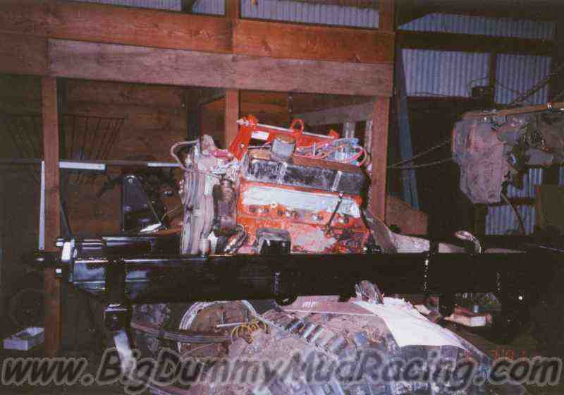
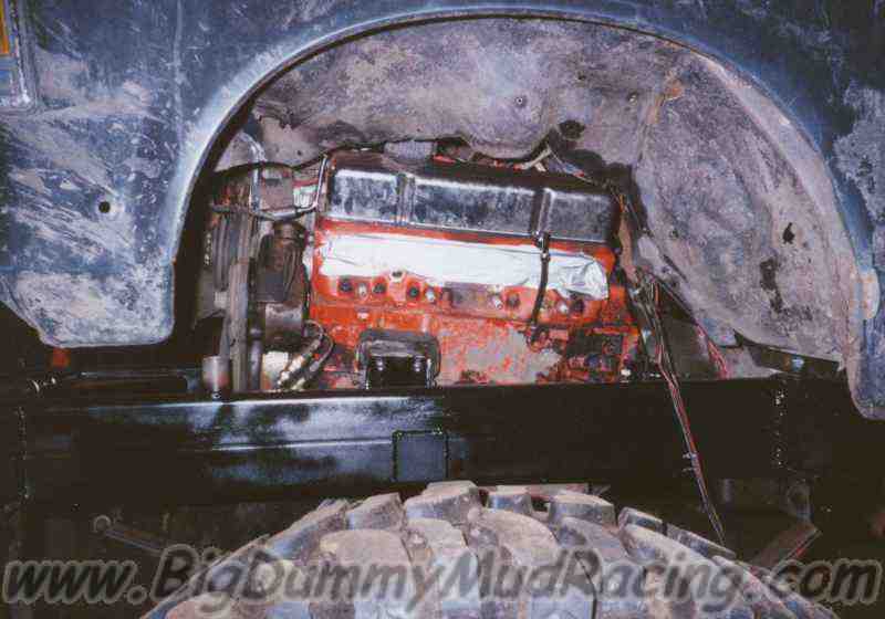
If you have read through the history of Highlander, you now know that 
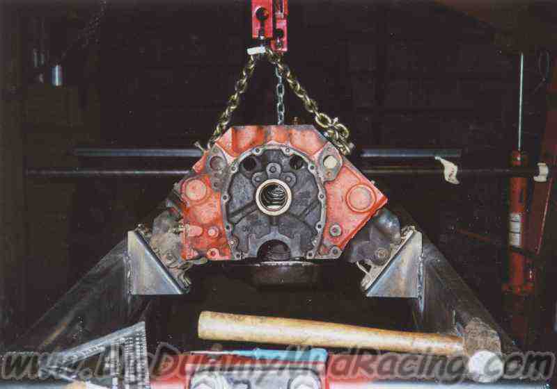
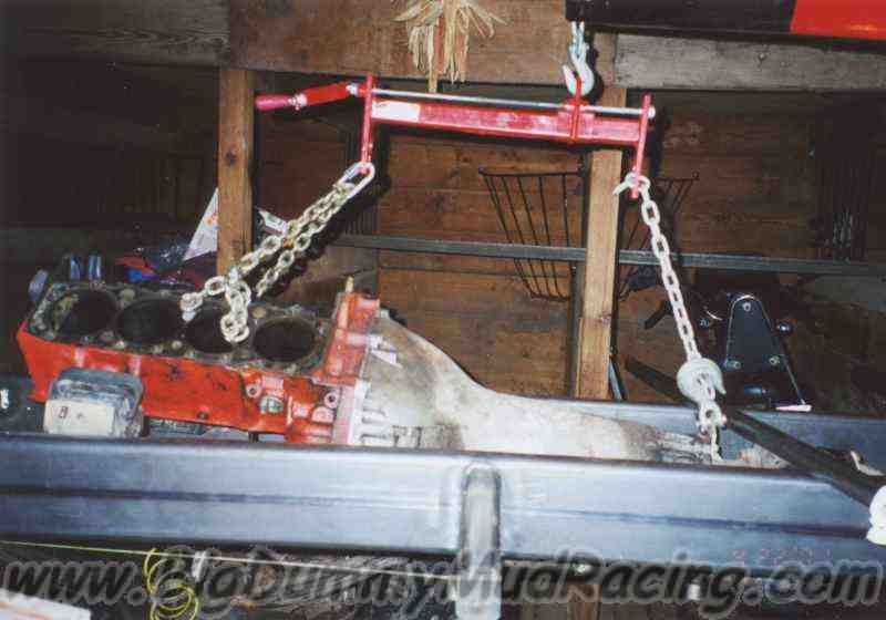
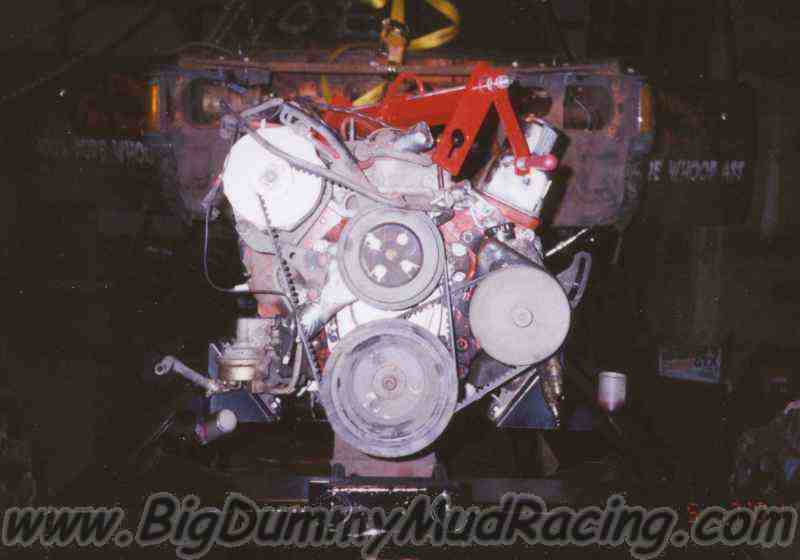
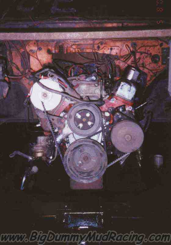
we toasted the original 350 at the end of 1999, and for 2000 we built a new small block - a 360 (350, .060 over) that should be capable of 475 HP and 450 ft-lb of torque.  As we all know, as soon as you move up another level in power, you find out all sorts of weak links, some of which you may have fixed once or twice already.  The weak link that the new motor found was the frame.

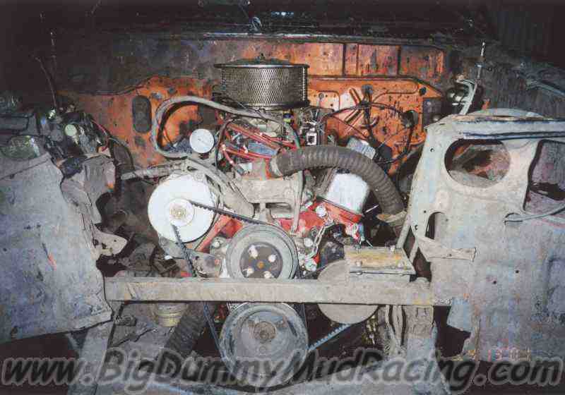
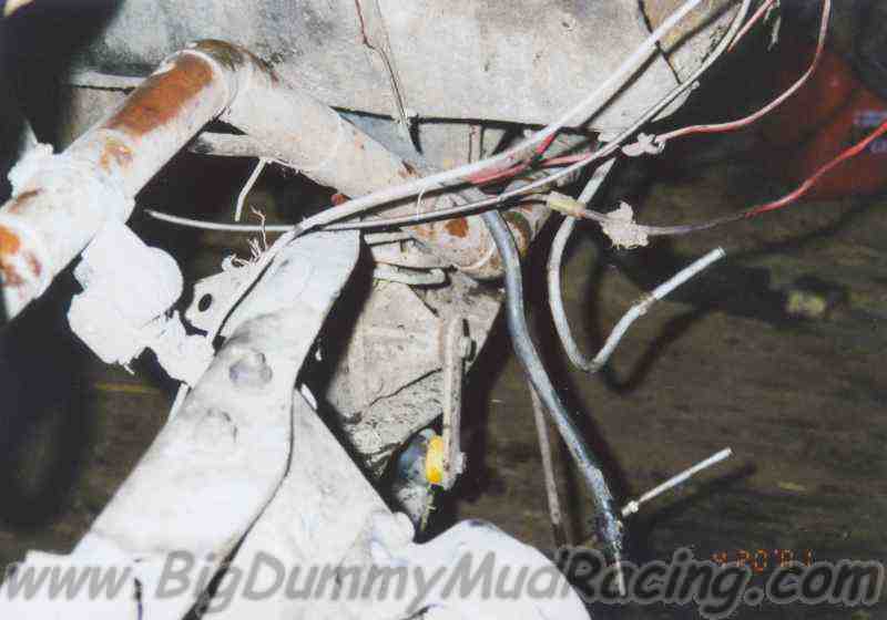
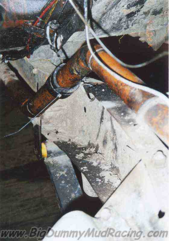
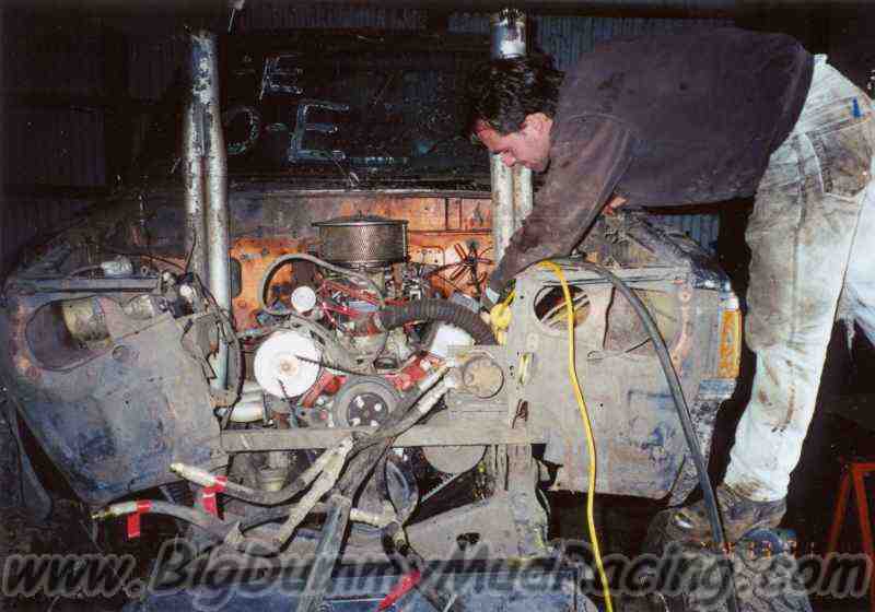
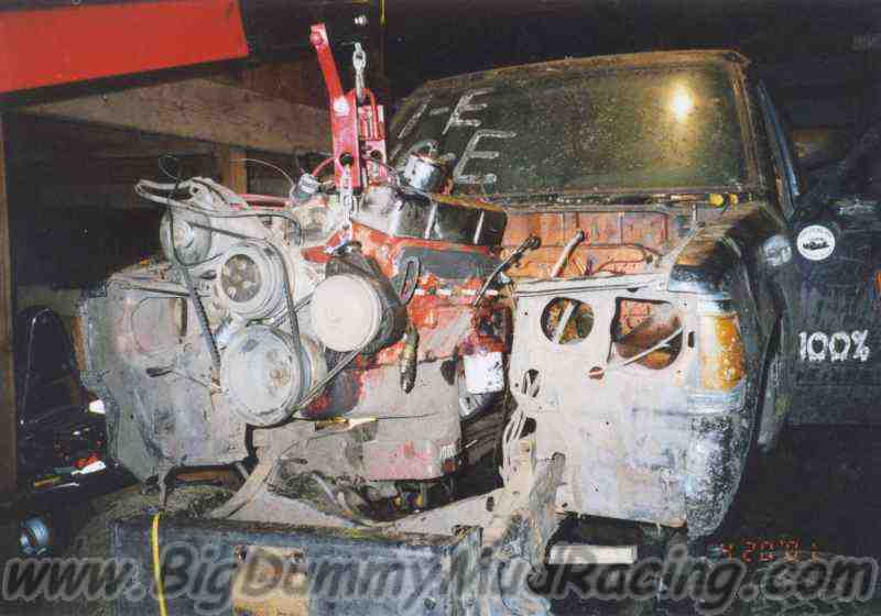
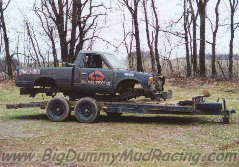
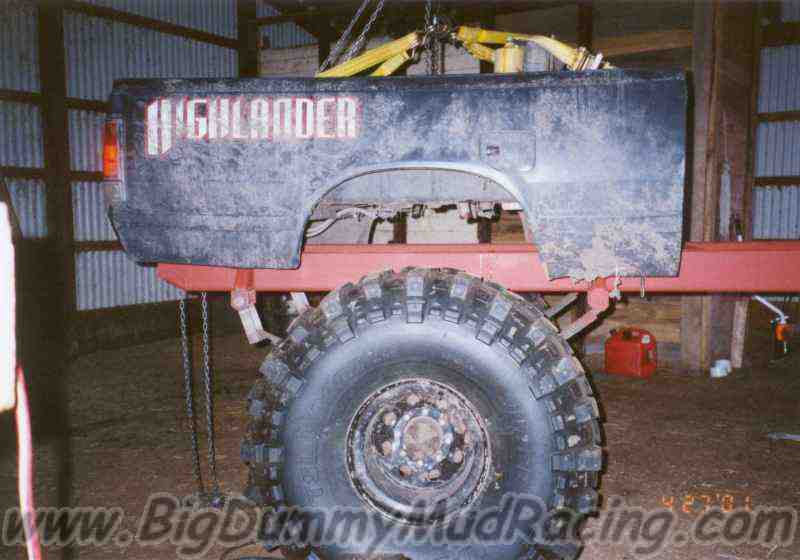
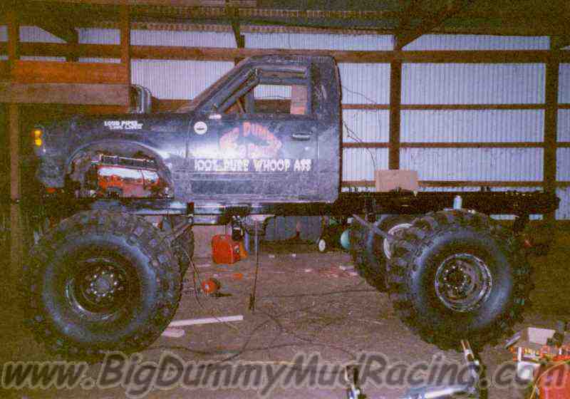
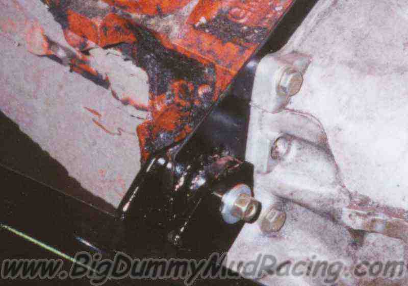
Highlander was built on a stock Blazer frame, which had taken years of abuse that it was never designed for, but the new motor was able to propel the truck to new heights - literally - and the frame wound up on the losing end of a 3' flight during the Memorial Weekend run of 2000.  

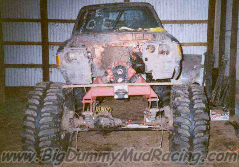
We ran the truck for the rest of the weekend, but after the event, we decided that the frame needed to be fixed before running it 
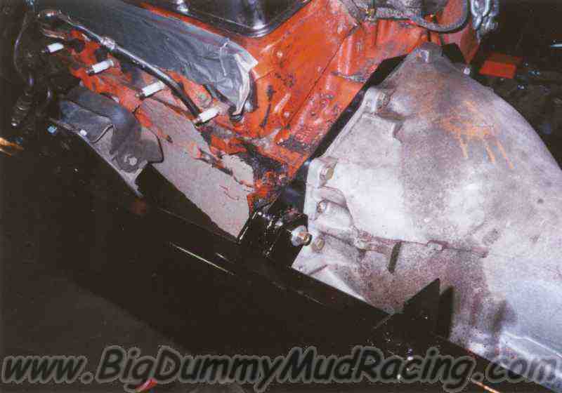
anymore.  At that point, with the new motor, tranny, rebuilt transfer case, and everything else, it seemed just too risky.

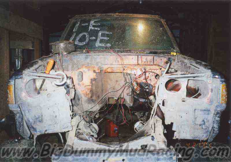
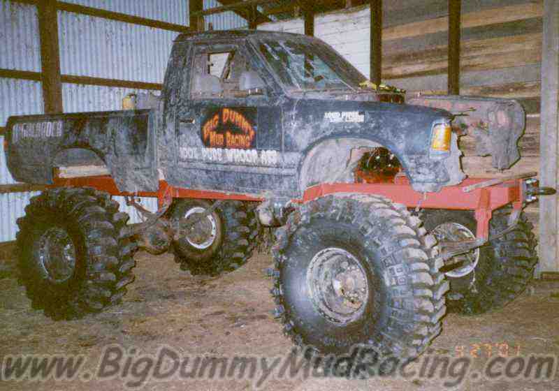
The truck sat out the rest of 2000 as Jason and I sorted out it's future.  It had become obvious to both of us that things were just getting too difficult to carry on running the truck together.  In 
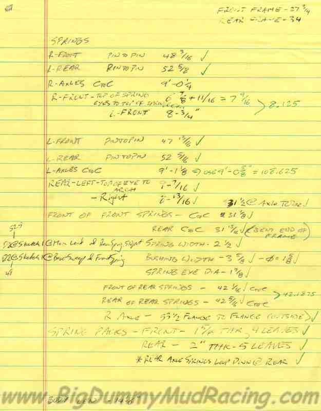
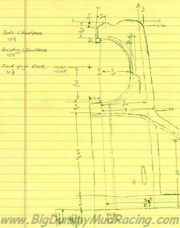
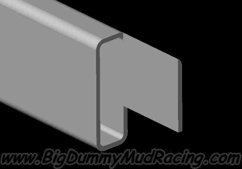
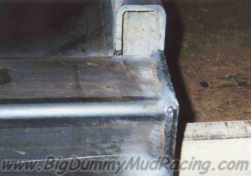
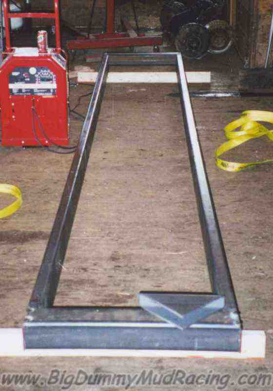
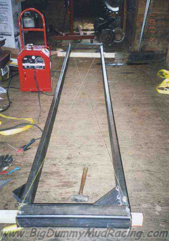
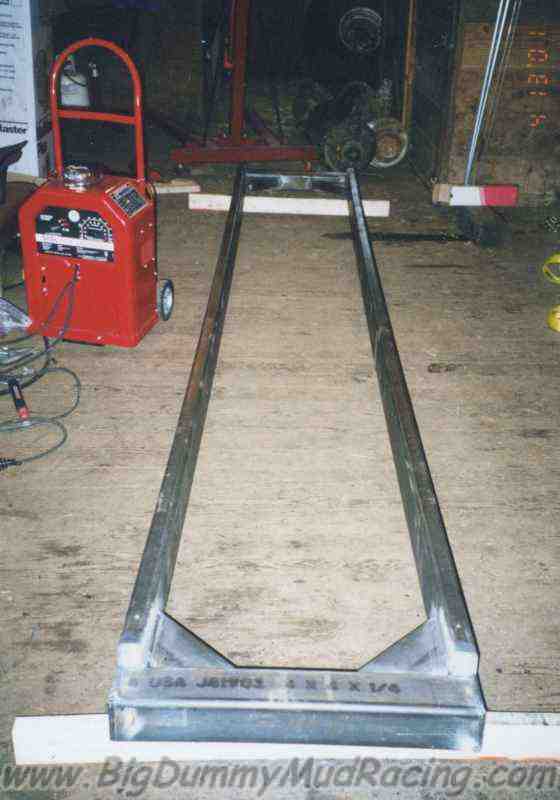
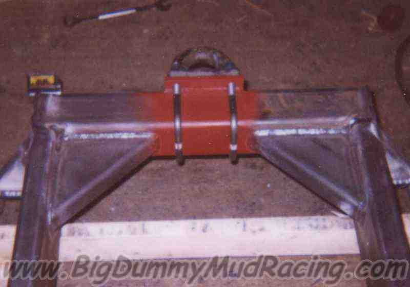
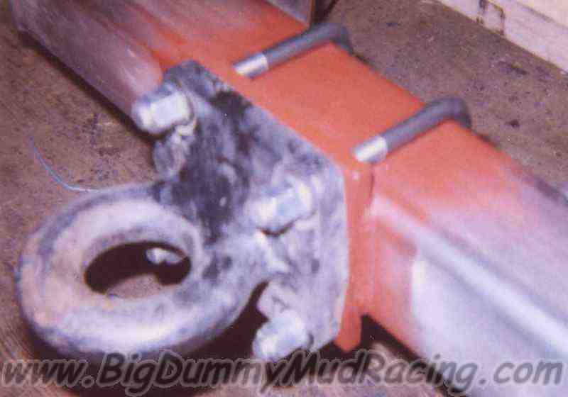
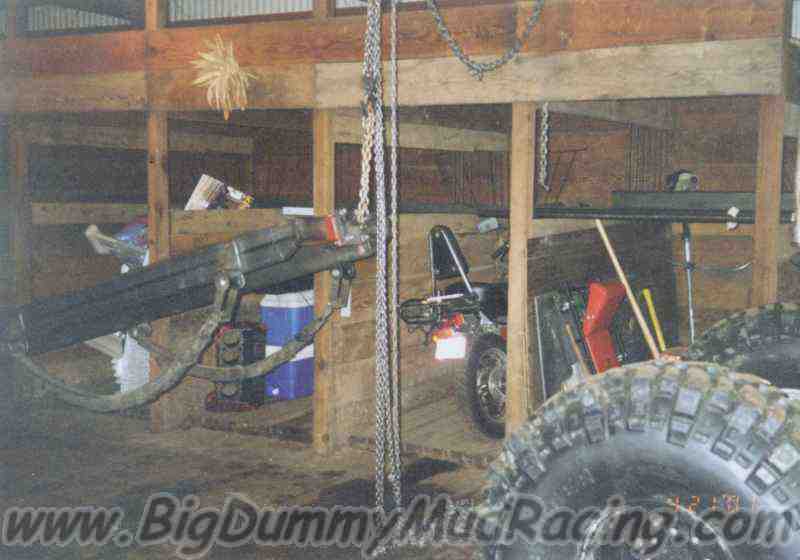
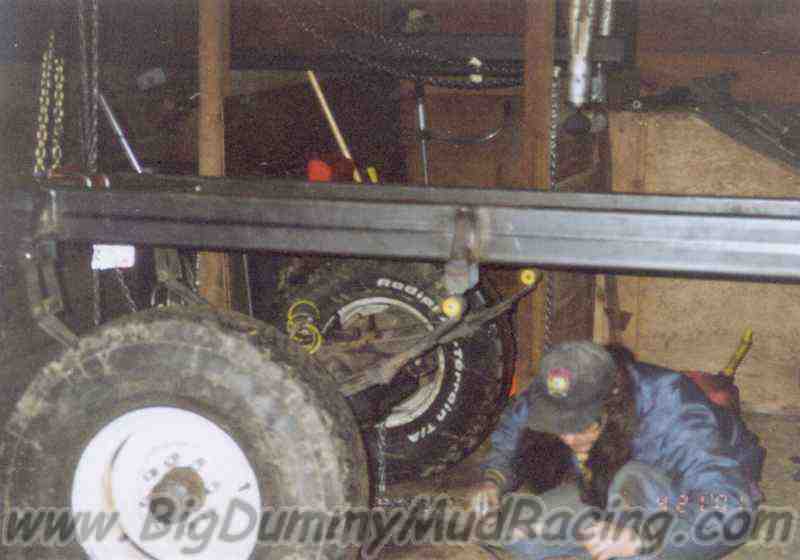
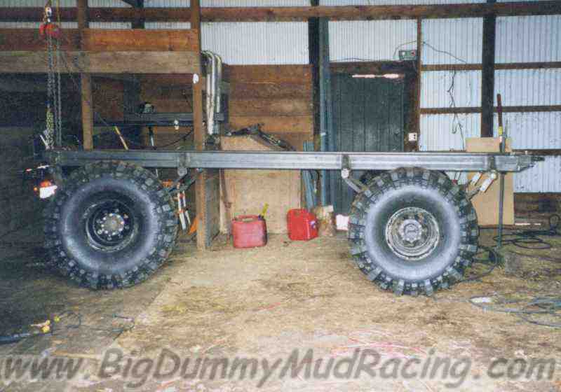
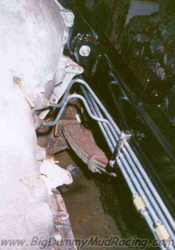
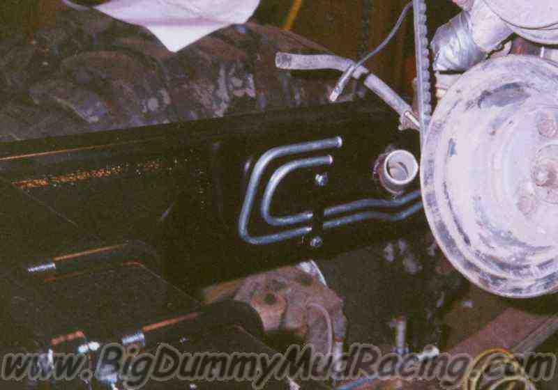
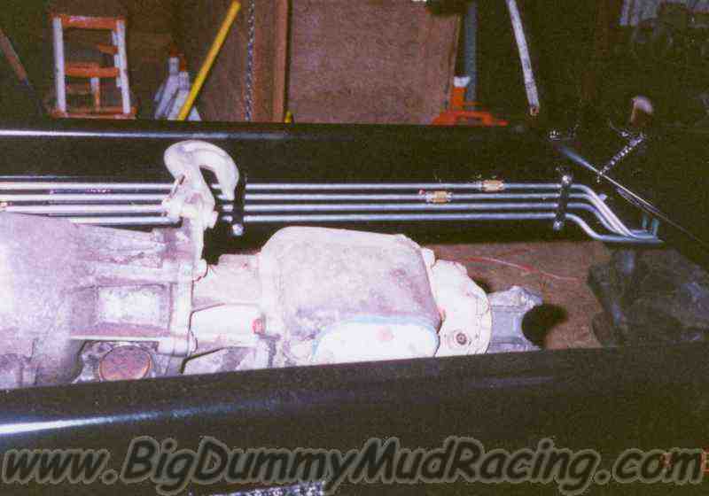
the end, I bought out Jason's half of the truck.  Before the frost 
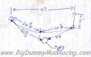
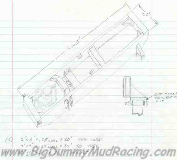
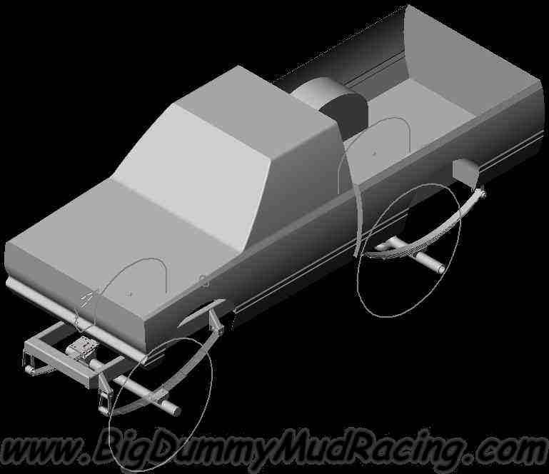
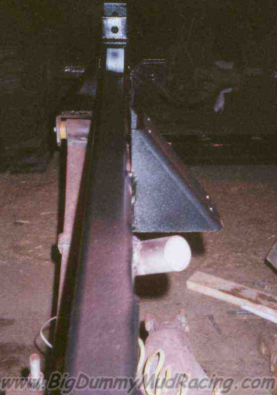
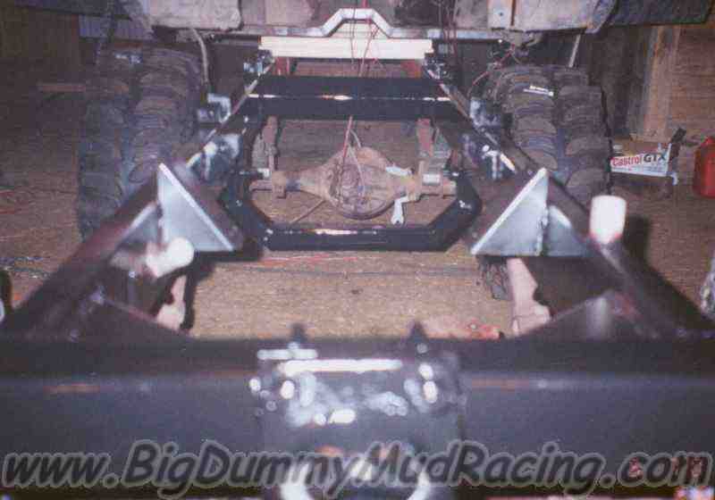
was out of the ground in the Spring of 2001, I started on a brand new frame for Higlander.

Over the four years since we built Highlander, the frame had taken a real beating.  By the time that the Spring of 2001 rolled around, the front arms of the frame had been bent so badly that the valve covers were touching the firewall.  

In fact, I fired it up for one last little romp in the snow before the end of winter, and at the end, the line for the oil pressure gauge got pinched off between the valve cover and the firewall.

Here you can see how twisted the front clip is, due to the bend in the frame


In these two shots you can see the most visible part of the bends.  On each frame rail, the upper leg of the "C" channel buckled, allowing the frame rail to bend outward, twist, and bow.

I spent some time before starting the new frame trying to understand the reason why the frame bent where it did, as the height of the frame in this portion is about 7", and both bends occurred between the two spring eyes.

It turns out though, when you look at what the truck was doing when most of the bending happened, things make sense.  Most of the bending was due to a noseheavy landing after catching 3' of air.  When we landed, the front cab mounts would have been nearly directly under the weight of the cab, and would have taken most of the force from not only the cab, but also the occupants.  Since the cab mounts couldn't bridge across the frame at that point due to the transmission being in the way, all of this force was converted to a twist in each frame rail - at a point where it was the furthest away from a crossmember.  Since the frame is an open C channel, it has very little resistance to twisting.  The end result is that the frame failed due to the weight of the cab twisting the frame rails, not from simply bending upwards. 

Ok - Now on to the good stuff!

Prep

One of the hardest, and most important parts of the process is the preparation, and design of the frame.  This must be the first step since you can't build anything until you know how you want to build it.  It also must come before any teardown, since you will need to measure all sorts of things on the truck, and you want the measurements to be as accurate as possible.  Though there are a few things that you may not be able to measure until you have better access - such as the motor mounts.

Just what to measure depends on the vehicle, and what is important to you in the finished product.  The axles and springs always need to be measured in detail.  Things like distance between springs, arch height, leaf width, eye-to-eye distance, bushing ID, and bushing length are critical to determining exactly how the springs and axles need to be mounted to the new frame.  There are also numerous measurements that are critical to properly placing the body.  The easiest way to make these measurements is to choose a point on the truck to be "0".  Then, make every measurement from "0" to the point of interest.  Then to find the distance between two points is simply found by subtracting one from the other.  Things that are important here are the location of the motor mounts, firewall, front and rear wheel well centerlines, front of the engine compartment (in our case - none), front axle and rear axle.

These are a few samples of the notes and measurements that I took.  Once I had enough parts of the truck measured, and I had sketched out a design concept for the frame, it was time to get serious...


I was then able to take all of the dimensions, and "build" the new frame on the computer.  This allowed me to move everything around until I was completely satisfied with how things fit together.  It also meant that once I started building the frame, most of the work would actually go to building it, instead of trying to lay it out - and hoping that it was right.

It also was good work to be doing during the winter.  After all, I do have a roof over my shop, but I don't have heat!


Here are a few of the major features that the new frame will have:

Coolant Through Frame design
The frame rails will be sealed, so coolant can travel between the motor and radiator through the frame.  This will eliminate the need for a separate set of tubes - reducing cleaning time, expense, and mountings.  It will also provide less restriction to flow, and extra surface area for heat transfer - if I'm in water up to the frame I won't even need the radiator.  The coolant capacity will also go up from about four gallons to about seventeen gallons, which will reduce the temperature spikes when I spend a lot of time on the go pedal.  To help make sure it never overheats, the radiator gets a 26 PSI cap, which will increase the boiling point to over 270°.  After all, with 17 gallons of coolant, if she ever blows - we'll all see Old Faithful without traveling to Wyoming!  The only other down side is that nothing can be bolted to the frame directly.  In order to mount to the frame, a bracket will first need to be welded on.
Front axle spring shackles in front
The new frame will have the shackles for the front springs in the front.  By putting the shackles in the front, the springs actually swing forward as they compress, requiring less spline travel in the driveshaft and reducing the risk of bottoming out the driveshaft travel.
      -- Note:  Later in the year, I discovered a small flaw in this design - Click Here to see what, and how it was fixed.
Mid Mount motor torque plate
I'm installing a mid-mount motor torque plate this year.  In the past, we kept the motor from twisting too much by chaining it down, but I have always been a little nervous that we would crack a head casting, or rip out the threads.  The torque plate will eliminate that risk.

Tear Down

Now that the frame was designed, it was time to get to the real work.

The first step was to pull out the motor, transmission, and transfer case, as well as nearly everything else that was in the engine compartment (or what was left of it).

Here you can see Nick tearing out the orbital steering valve, along with it's octopus like tangle of hoses.

Once all of that had been stripped out, the rest of the truck was rolled back out of the way for a while so that the new frame could be built.

Fabrication

The new frame is constructed of 2 x 6 x 1/4 rectangular tubing rails, with 4 x 4 x 1/4 ends.  The new frame rails will be 2-4 times stronger than the old frame rails were in bending, and immensely stronger in twisting.

In each corner of the frame, I went a little complicated.  I wanted to join the two sizes of tubing in a way that capped off the ends of each tube, made a clean transition from one to the other, and would be a little stronger than just welding one to the other.  The result was what you see to the right.  I cut the rails to the length of the entire frame, and then cut another 4" off of parts of the tube, leaving a 4" x 4" tab extending from what will be the outside wall of the frame.  This leaves a lot of material to connect the two tubes together, as well as creates a cap for the 4x4.
  

Since the coolant will be running through the frame rails, I need to make sure that the ends of the 2x6 are water tight.  Instead of relying on the multitude of welds that will be on the corner between the sides and ends, I decided to plug the rails with left over pieces of 1/4" thick steel.  That way, I will only need to make sure that the plug seals are watertight.  After welding in the plugs, the rails were pressure tested with air, and checked for leaks with soapy water.  I fixed all of the leaks that I found, and then was able to move on.  The picture to the left shows the plug, and the corner joint about 1/2 way to completion.


Next, the frame was laid out on the floor, and tacked together.  Here you can see one of the corner braces before it gets welded in.  The braces are cut from the same 2 x 6 tubing that the frame rails are made of, so they should be more than strong.

Once the frame is squared, one corner brace is tacked into a corner to make sure things stay squared while the frame is checked for twist.

Strings were run from corner to corner, and each end shimmed until there was no twist from end to end.  Once the twist was removed, the rest of the corner braces were tacked into place.


Then, the corners were welded by welding one bead on each corner, until all of the joints were welded, and all of the corner braces were welded in.  By moving from corner to corner, the chances of warping, and the frame winding up crooked are minimized.

The shot on the right was taken once the process was completed. At this point, the frame looks kind of narrow and long, but I assure you, it is the right size!


The next step was to cut the small triangular pieces that would fill in the step from the 2 x 6 to the 4 x 4.  The brackets and braces for the spring mounts were also cut at this time.

Some of these cuts wound up getting fairly interesting as it got harder and harder to hold on to the pieces at the angles that were needed.


To the right, you can see the triangular corner fillers have been welded in, and so have the spring brackets.


The spring brackets are, like everything else, pieces of 2x6, and 4x4 tubing.


The shackles themselves I made 6" long, instead of the stock 4".  This really should have been done earlier, since the heavily arched 12" lift springs need more shackle travel to work right.

The widths of the front springs actually are wider than the rear springs too.  This required me to put a slight step in the shackles for the front springs, but otherwise, the shackles and spring mounts are all identical.

The shackles were made from 1-1/4 x 1/4" barstock.  The tube that connects the two legs has an ID of slightly over 3/4", and allows for an inner sleeve that is made of 9/16 ID x 3/4 OD tubing.  The sleeve is slightly longer than the width of the base of the shackle, which allows the bolt to be tightened without closing the ears of the spring mount enough to restrict the movement of the shackle.

I didn't have time this year, but I plan on adding a grease zirk to each of the shackles as time goes on.

This was also a good time to add the pull points.  The new pull points are very similar to the ones that I built for Brian's truck last year, and are the reason why


I am using 4x4 tubing in the front and rear.  The tow eye is attached with custom made 5/8" u-bolts, using the same material that is used in axle u-bolts.  The u-bolts are then fed through holes on a 1/2" steel backing plate.  The plate and the holes are there to make sure the eye doesn't slide around on the tubing if I get pulled at a funny angle.


Now that we had the basic frame together, the next step was to attach the axles, and actually make ourselves a rolling chassis.  This, of course, meant that the old frame now needed to be separated from them.

Here you can see the old truck has been reduced to a shell of it's former self, with just a wrecked frame, and the body remaining.

Below, you can see a few shots of the first installment of the axles.  They will be pulled back off later, once I have a chance to look at the driveline angles.


The next step was to build the motor and transfer case mounts.  I spent a lot of time on this step, because I wanted to be absolutely sure that the motor was going to be in the right place the first time.  I spent a lot of time measuring the old frame, the body, the distance from the old motor mounts to the body, the positions of the axles, and anything else that I though would be important.  Nick even came up to help out, and debate the complexities.

After all of that, I went back to my plans, and drew up motor mounts that would fit.  Actually Nick convinced me to draw them 1/4" taller "just in case".

I tack welded the new motor mounts onto the frame (after a bunch more measuring, of course!)  Then we attached my spare engine block to the tranny, and hoisted the assembly into the frame.

Once I corrected the position of the mounts for the angle of the motor, everything was fitting fine -- thanks to the extra 1/4".  Then I welded the new mounts on.

And hoped that all of my measurements were correct...

At this point, the rest of the major welding tasks were up to be completed.

The new transfer case mount was built out of 2x3x1/4 rectangular tubing, so that the stock style urethane mounts that we bought last year could be used.  (with some slight trimming)  The U shaped mount was attached to the frame with a pair of 1/4" plates on each frame rail. 

An additional crossmemeber was added to the frame a little ways behind the end of the transfer case.

The mid-mount motor plate mounts were also added.  The mounts use a round urethane bushing with steel sleeves on the inside and outside.

And the old mounting blocks were ground off of the front and rear axles to make way for the new ones.  For the rear, I actually re-used the old blocks, but they had to be re-positioned to accomodate the narrower frame width in the rear.  For the front axle, the old 20° shim blocks that had been added now rotated the axle too far (due to having the spring shackles in front).  The fix was to build a set of 10° blocks to replace the old ones.  The pin holes in the front mounts were also moved 1", so that the axle would sit further forward.  Here are some shots of the finished axle work.

The next step was to bring the old frame & body back in, so that they could be separated.  The body was then placed (temporarily) on the new frame, and the old frame was put out to pasture.

You can start to see what the truck's new look will be.

The new cab and box mounts were built next.  After four years in the mud, the cab mounts were shot, so both the front and rear cab mounts were replaced with rectangular tubing, welded or bolted into the cab.

Next, I had to locate the positions of the water inlets and outlets in the frame.  So I dropped the real motor into the frame, but just for a little while.

While everything was being moved around, I dropped a coat of paint on it too.

Here you can see the completed water inlets and outlets for the motor.

You can also see the rest of the frame in the last bare shot of it.  From here on out, I do a lot more bolting than moving.

Before I could slide the body back to it's position though, I had to route my fuel and tranny cooler lines.  To mount the lines to the frame, I built brackets out of 1/2 x 5/8 barstock, with slots milled out for the 3/8 & 5/16's lines.  The brackets were welded to the frame, and the tubes clamped in with a piece of 5/8 x 1/4.

The end result is a nice clean look, and lines that won't get snagged by anything in the pit.

Then it was time to bolt in the body - for the final time!!!  To the right you can see various shots of the last few pieces going together.  

All of those pesky little details were all that was left.  The accessories were bolted back onto the motor, the final connections were made to the fuel, tranny cooler, and cooling lines.  The electrical lines were run to their various places, and secured with wire straps and either rivets, or self tapping sheet metal screws.

New driveshafts were also in order, so for the second year in a row, all of the old driveshafts had to be cut up and re-sized.  I have one spare rear shaft, and two spare fronts, so before I could roll for Memorial weekend, I made sure all 5 were reworked.

I managed to finish the truck with about a week and a half left before Memorial weekend.  I spent that time testing, and double-checking some of the crucial components.  The last thing that I wanted to do was to get up to the first run with the new frame, and discover a major problem that would prevent me from running.


Next stop...  Onamia!  Click here to see the first event with the new frame.


Photo Album Highlander Links Guest book
Photo Album Highlander Links Our Trucks Guest book Suppliers Reference The S__t List
               
Link Exchange Member LinkExchange